Quick Links:
- Introduction
- Step 1: Conceptualisation – Every walk begins with a step
- Step 2: Technical elaboration – designing the matching puzzle pieces
- Step 3: Sampling – getting a first impression
- Step 4: Test field – without tests, no safety
- Step 5: Assembly – efficient preparatory work paid off!
- Step 6: Commissioning & inspection – now it’s Time to Run!
- Step 7: Review – lessons learned / recap
1. Introduction
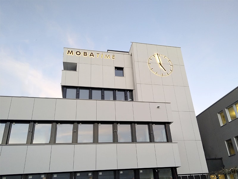
MOBATIME is producing a new and innovative facade clock. We are very excited about this challenging project, which has started in June and finished by the end of September. From conception and elaboration to installation and commissioning, you will gain an insight from our work. We also present our newly developed prototypes, which were used in this project.
Step 1: Conceptualisation – Every walk begins with a step
The concept phase is the first step in any project. In principle, the ideal solution for a customer is determined based on the product specification. A comprehensive preliminary clarification is indispensable in the run-up in order to record all relevant requirements. Only through the situation analysis a suitable solution could be developed.
In this project, we work hand in hand with the customer, the architect, the timber constructor and the façade builder. Due to specific structural specifications and unique architect’s design, it was clear that a standard solution was not suitable. Unlike ordinary façade clocks, the client’s wish was that the clock should, not only have the hour indexes and hands illuminated, but every single minute indexes with illumination.
Structural difficulties out of this project:
- The area behind the façade elements (rear ventilation) was no longer accessible after completion of the construction work.
- Direct mounting of the indexes on the façade elements was not permitted.
- The façade opening to the mounting point of the movement was subject to large structural tolerances.
- The available installation depth for the movement was limited to 250mm.
Due to these four main reasons, our specialists had to find a solution that could be adapted to the structural conditions and at the same time be easy for installation and maintenance thereafter.
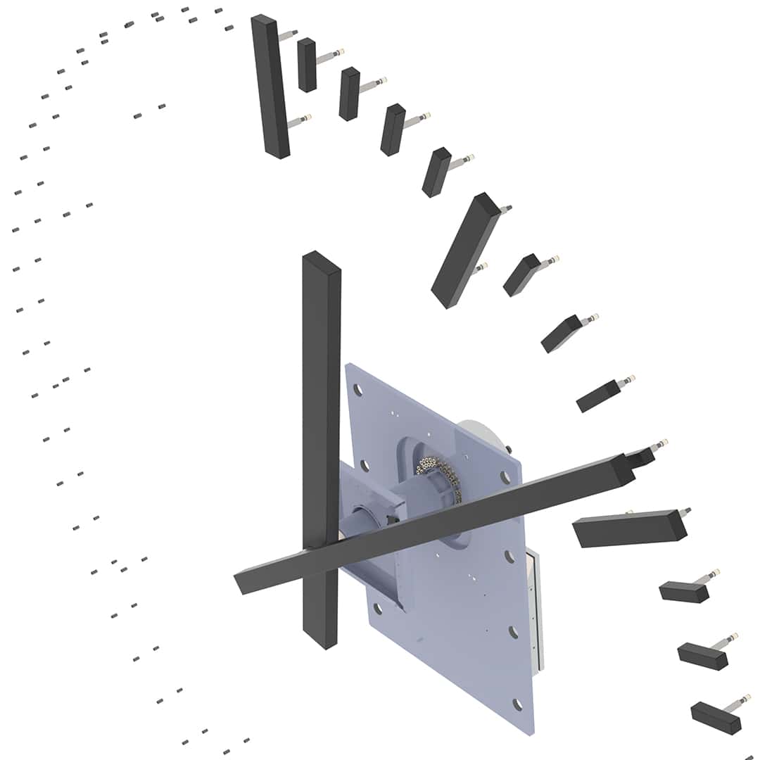
Our team found a solution to these challenges after careful examination of the situation, which received customer approval:
- a special mounting device & housing for the movement will be designed to compensate for the radial deviations. The cable routing will be designed in such a way that the nodes are accessible and all cables can be replaced individually.
- the indexes will be mounted on the façade substructure so that the façade elements remain load-free. Due to the limited wall thickness, it was decided to equip a movement that is suitable in terms of installation size and performance with a newly developed additional module for the rotary feed-through for the supply of the LED illumination.
Step 2: Technical elaboration – designing the matching puzzle pieces
Before the start of sourcing of appropriate material, all individual parts and assemblies must be simulated technically & in design prospect. Our design department was responsible for this in the elaboration phase. During the elaboration phase, the ideas and specifications from the concept, which forms the basis, are transferred into production documents. Many a solution that seemed simple in the conception phase turns out to be not so trivial during the simulation.
The client wanted an illuminated end-of-aisle clock according to the renovation of their building structure. It was important to them that easy management could be guaranteed and that the employees were not disturbed by the noise of the clockwork during their work.
In order for the two clock hands to be illuminated, power must be transferred from the fixed power supply units in the buildings to the rotating hands. In the case of endless rotation, the supply voltage can be transmitted via so-called slip rings. However, according to this unique requirement, the MOBATIME standard product intended for such applications had the following incompetence:
- the movement, which is designed for a clock diameter of 5m, can only be synchronised via pulses and is therefore not self-aligning. Control via the self-setting MOBALine signal or even a network was not possible.
- The movement has large external dimensions. Due to the design of the movement for high torques, the noise emission was in a critical range.
Prototype – new slip ring assembly enables illuminated hands
Our design team therefore had to look for a new solution, which they found. The DMU350 movement is now to be used for this project. This extremely high-torque and smooth-running movement is particularly suitable because it could be synchronised via the self-setting MOBALine signal. However, the DMU series does not have an integrated power feed-through and thus no possibility to illuminate minute and hour hands. In order to meet the customer’s requirements and to offer a solution that is as inexpensive as possible, the design team decided to add new feature for the movement. The DMU 350 could be redesigned with this modular add-on and now has the option of illuminating hands.
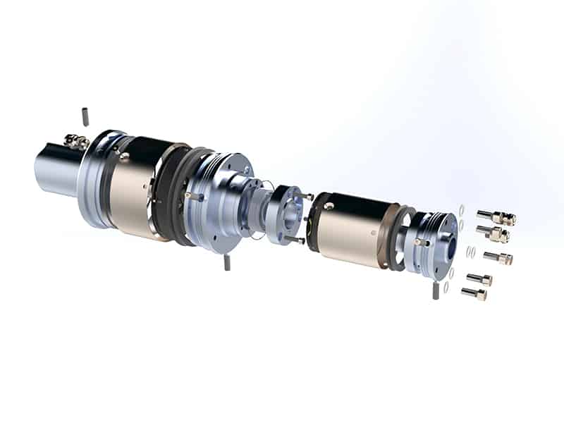
In a nutshell: What are the advantages of the new slip ring accessory?
- scalable unit for rotary feed-through for LED illumination of minute and hour hands
- modularity – the unit can be installed on standard products as an option or retrofitted to existing systems. Use of proven standard products as basic clockwork remains possible.
Prototype – new type of assembly unit for facade clocks
In addition to the new slip ring assiette, another prototype was used in this project. It was a special clockwork assembly device. With this adjustment mechanism, it was possible to subsequently shift the position of the movement axis in vertical and horizontal direction. Structural dimensional deviations could thus be compensated for. The requirements on the accuracy of the on-site assembly section were thus reduced, which had an advantageous effect on the costs. It was thus possible to carry out the positioning flexibly without having to rely on exact structural specifications. For the company carrying out the installation, this means a simpler, safer and less stressful installation. Unattractive delays and additional costs caused by inaccuracies could be effectively prevented with this device.
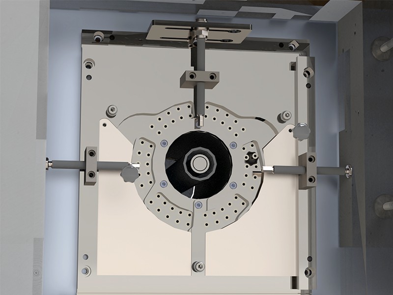
What exactly does this installation device look like?
Essentially, the positioning device consists of two plate-shaped slides, one of which could be moved in a vertical direction and the other in a horizontal direction. The adjustment range was +/- 40mm in both directions. Via threaded spindles, the movement axis could be adjusted with the movement dismantled without much effort. The adjustment mechanism was mounted on a base plate, which was screwed to the concrete wall using levelling screws. The complete cable routing for the illuminated indexes was also integrated in the unit. The total of 60 supply cables for the LED lights are laid from the clockwork mounting plate, which was accessible from the other side, through the so-called coaxial tube (double-walled tube lying on the clockwork case) into the area of the rear ventilation of the outer façade. The centralised routing of all cables through the movement axis eliminated the need for additional on-site breakthroughs in the façade. On the construction side, only a single on-site breakthrough in the centre was required for the entire clock installation. The coaxial pipe was designed in such a way that the complete movement, including the slip ring, can be inserted from the inside of the building. This will be eliminating the need for time-consuming during installation on site.
The hands and indexes are the only elements to be mounted from the outside of the building. Since the 48-minute indexes and 12-hour indexes cannot be mounted directly on the facade elements for static reasons, a round mounting plate resting on the substructure was provided into which the spacer bolts were screwed. The wheel-like mounting plate was positioned vertically and radially through to the movement axis by being inserted in the center over the coaxial pipe. Therefore, when the movement axis was moved with the adjustment mechanism, the position of all index mounting points also changes at the same time. This design greatly simplifies the manufacture and assembly of the components on the building side. The only requirement for the facade builder was the dimensional accuracy of the hole pattern in the facade panels.
Indirect index and pointer illumination / cable routing
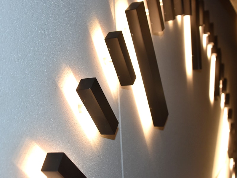
All indexes and hands were indirectly illuminated with LEDs. This means that the lighting elements were mounted on the back of the hands or indexes and the wall itself would be illuminated. This principle allows the contours of the clock components to be emphasised very clearly. To ensure ease of maintenance, each index was individually wired and the supply cable was routed to the accessible area below the movement. At this point, the cables were brought together and grouped into a total of four LED light circuits: All hour indexes, minute indexes, minute hands and hour hands. The light circuits were powered by independent power supply units and can be dimmed and switched individually according to the customer’s preferences. The implemented individual cable routing has the advantage that each cable can be replaced individually in the event of a cable break. All nodes are located in the access area to the movement. It is advisable to simplify all maintenance-intensive processes, especially in applications where access to the movement or the cabling can be described as complex.
Step 3: Sampling – getting a first impression
Assessing luminaire effects on the basis of 3D CAD models and renderings was not always easy, because a large number of factors influencing the appearance couldn’t be captured in the computer-designed models. For this reason, it was decided to carry out a sampling of the lighting elements (hands, indexes and illuminated letters). A sample element had to be created so that the sampling could take place on the customer’s roof. For the sampling of the façade clock, not only the client, but also project managers and the management were on site. To avoid having to assemble a complete clock, a 3/4 model was produced. For this, only a few indexes as well as 2 letters with different sizes were used. The same façade surface and façade panels were used for the sample element as were used for the finished building. The substructure of the sample element was identical in structure to the finished façade. It was therefore also possible to show the special cable routing and the installation situation for the clockwork on the model and to discuss this with the customer. For the lighting, special care was taken to ensure that the luminosity and size of the façade clock was optimally visible at an acceptable distance and met the client’s requirements.
The customer was very satisfied with the lighting effect and the visual impact from a distance. Therefore, we were able to get the approval for production and started with the implementation.

Step 4: Test field – without tests, no safety
Producing a clock without testing & validation was not a way for Mobatime. No matter what dimension the Clocks or movements have, every single product is subject to a test & validation lasting several days. In addition to the running behaviour, the mechanics and electronics were also checked. Only clean and conscientious testing could ensure that the product complied with the requirements and standards. In this project, the two DMU350 movement were running for several weeks, including slip-ring assemblies and complete housing. The whole process was closely monitored. Any unexpected discrepancies in the components installed later could thus be detected and rectified at an early stage. Various findings on the indexes, their installation, the cabling and the illumination effect could be derived from the sampling element.
What influences / increase the probability of a malfunction?
The following factors can increase the probability of a fault in façade clock:
- Wind loads
- Vibrations
- Heat
- Cold
- Humidity
- Unfavourable combination of several influences
Thanks to Mobatime rich years of experience and knowhow out of hundreds of its kind of projects, we know which design elements ensure that such sources of error are minimised or even eliminated.
Step 5: Assembly – efficient preparatory work paid off!
The mounting plates for the clockwork were installed on site. The two mounting plates are placed on the masonry below the timber construction, so that this could be installed hand in hand with the timber constructors. The mounting ring was placed below the façade elements on the support grid, the so-called substructure. The substructure therefore had to be installed beforehand. This was not yet necessary for the glass fibre concrete façade panels. The interaction between MOBATIME and the façade builder thus had to work hand in hand. The installation of the first glass-fibre concrete elements over the mounting plates was a key moment, as it was only later that it became clear whether the spacer bolt holes matched and whether the planning and interaction during the design worked.
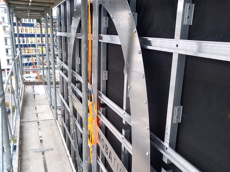
We were pleased to find that the holes matched to the millimetre and the façade planning and execution was highly precise. The mounting elements on the west side were prepared so far that only the spacer bolts have to be set and the letters connected.
We were then able to complete the installation of the substructure mounting rings with the setting of the spacer bolts. This means that the final assembly of the two clocks could take place.
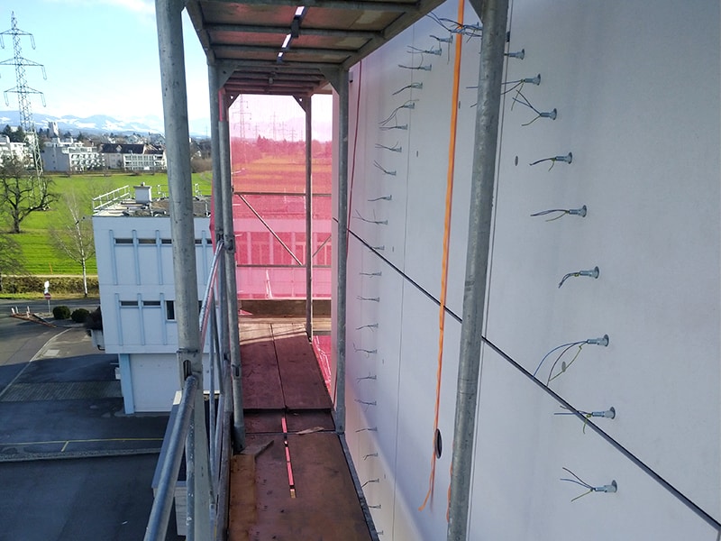
Thanks to the central wiring of the clock indexes through the coaxial tube, all the connecting cables from the power supply units to the lighting elements could be prefabricated and preassembled in the factory. This reduced the effort for on-site cabling at the construction site to a minimum. Thanks to the comprehensive preliminary clarifications with the electrician in charge, the supply and signal lines were also ready at the master clock and the clockworks.
Step 6: Commissioning & inspection – now it’s Time to Run!
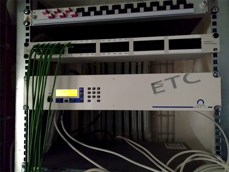
Commissioning & inspection is the last step of the project. The assembly was completed, wiring set and the clockwork connected to the master clock. A final check is made of the work done so far. Now only the facade clock including hands and indexes had to be powered. One of our experts was on site and expertly carried out the commissioning. The customer was carefully accompanied by us during this step.
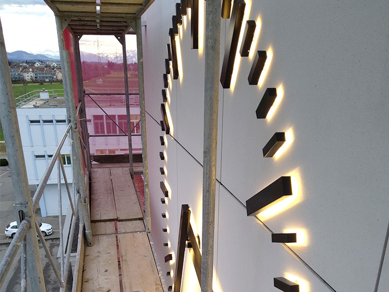
In addition to the commissioning by our expert, the customer was trained so that they are able to operate the clock including brightness control and manage the same independently when needed.
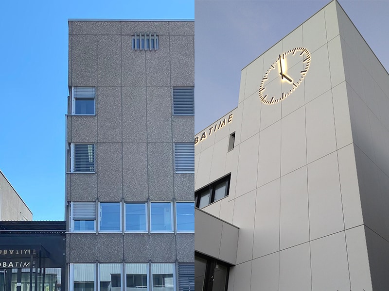
At the touch of a button, the clock was illuminated and shone in all its glory. Commissioning for this project took no more than 15 minutes. No corrections were necessary, which indicates that all the previous processes were implemented properly. This way the stress of both, the project manager and the client could be avoided and they could now proudly experience and cheered up their new façade clock in action.
Step 7: Review – lessons learned / recap
The project, including the design phase, was completed in less than 4 months. It was important to the team that the cooperation with other craftsmen ran smoothly and that no stoppages were caused. Comprehensive planning was indispensable for this. The result was pleasing, as all deadlines were met from our side.
How can our customers be benefitted?
Two prototypes were used in this project, which had a successful impact on our customer. Firstly, the new development of the slip ring assembly, which allowed us to redesign existing movements with it. It is now possible for MOBATIME to equip almost all larger outdoor movements with the illumination function. This is a direct advantage for our customers, as more options are available and the best possible variant can be selected based on the requirements.
In addition, the new mounting device allowed us to simplify the preparation on site during the installation. With this device, the façade builder has more leeway and higher tolerance when breaking through the façade for the clockwork. We wanted to make the work easier and more efficient for everyone involved. Therefore, Mobatime invests in such subjects and tries to constantly develop further.
